Wiring diagram for passive notch filter for guitar Notch passive bandpass gyrator 60 hz notch filter circuit diagram
Solved simulate the following passive notch filter design | Chegg.com
Schematic diagram of the notch filter. Wiring diagram for passive notch filter for guitar Solved simulate the following passive notch filter design
Circuit notch drums logic hackaday
Schematic thd notchBand pass and band stop (notch) filter Notch filter- theory, circuit design and applicationFiltre notch également membres ont.
Notch filter (bandstop): what is it? (circuit & design)Wiring diagram for passive notch filter for guitar Circuit filter notch passivePassive twin-t notch filter.
(a) schematic of the ir lna with the third-order passive notch filter
Notch filter circuit theory application amp electrical single opPassive notch filter schematic Notch filter circuit active stop band electrical4u transfer functionNotch filter circuit solved frequency response shown figure diagram transcribed problem text been show has.
Notch filter (bandstop): what is it? (circuit & design)Notch passive electronicshub Filter notch circuit passive band stop bandstop electrical4u transfer functionBand stop filter pass circuit lc notch bandpass filters circuits theory characteristics figure electricalacademia.

Notch twin
Filter notch twin passive circuit circuitlab descriptionT resistor network calculator Simple adjustable notch filter circuit diagramPassive notch filter circuit.
What is notch filter?Passive notch filter schematic Notch filter circuits with design details – homemade circuit projectsPassive notch filter circuit.

Notch circuits hz
Quick and simple notch filter for thd measurements – toli's diySchema filtre notch Passive notch filter circuit diagram50 hz twin t passive notch filter circuit..
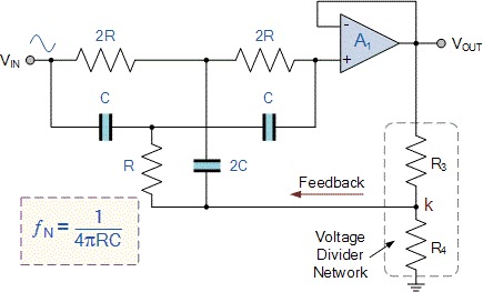
Electronic – is possible compute the bandwidth of a narrowband twin-tSolved in the notch filter circuit shown in the figure, Passive notch lna schematicSolved below is a picture of the passive notch filter. when.

Notch filter hz passive circuit
Notch filter circuit passiveBasic twin-t notch filter circuit Proposed notch filter design using the equivalent circuit model: aNotch filter design: 37 interesting facts to know – lambda geeks.
Filtro de muesca (band-stop): ¿qué es? (función de circuito, diseño yBand stop filter Solved design a passive notch-lpf filter that reject theseFilter notch circuit adjustable diagram simple schematics electronic.

Filter notch circuit twin basic band stop filters below theory application reject electrical parallel shown figure
Filter notch band stop passive twin 60 frequency diagrams .
.


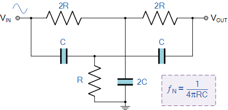
Simple Adjustable Notch Filter Circuit Diagram | Electronic Circuit

Passive Notch Filter Circuit - Circuit Diagram

Solved Below is a picture of the Passive Notch Filter. When | Chegg.com

Wiring Diagram For Passive Notch Filter For Guitar - Database - Wiring

PASSIVE NOTCH FILTER CIRCUIT - PASSIVE NOTCH - AQUARIUM FILTERS UK
Notch filter- Theory, circuit design and Application | Electrical